Level: Big project (Master's thesis)
GitHub Repository: https://github.com/JaumeAlbardaner/collision_avoidance_TFM
Grade: 5.75/6.0
Publication: https://www.iri.upc.edu/master_thesis/show/248
What are "Bumper(less) cars"?
Bumper cars are an amusement park ride consisting of several small electric cars designed to collide with one another. Nonetheless, the usual objective of an actual car is to avoid collisions. To achieve such a goal, different collision avoidance mechanisms are in use and under development today. To compare these algorithms, what a better place to run them than on an environment where colliding is the final goal?
Hence, bumper(less) cars is the name of the platform where bumper cars are kept away from their final goal: colliding.
Why bumper(less) cars?
During my stay at the Dependable Control and Decision group (DECODE) from the Laboratoire d'Automatique (LA) at the École Polytechnique Fédérale de Lausanne (EPFL), I was requested to implement a series of collision avoidance algorithms onto their motion capture system. The idea was to verify the results obtained in simulation on a real platform.
Algorithms
The algorithms that were considered for implementation in this project were the following:
- DWA: Dynamic Window Approach. Given the current feasible inputs of the vehicle, choose the series of inputs that will not lead to collision and will lead as close as possible to the desired configuration.
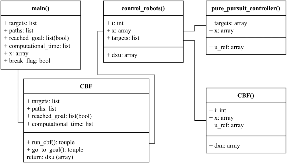
- CBF: Collision Barrier Fuctions. Minimizes the difference between the desired input and an input that will make the vehicle stay away from boundaries. For this algorithm boundaries are circles around obstacles that increase the cost of a trajectory to the point of solver's infeasibility.
- C3BF: Collision Cone Control Barrier Functions. Follows the same principle as CBF but rather than circles, the barrier function expands towards the controlled car if they are facingeach other, thus the cone shape.
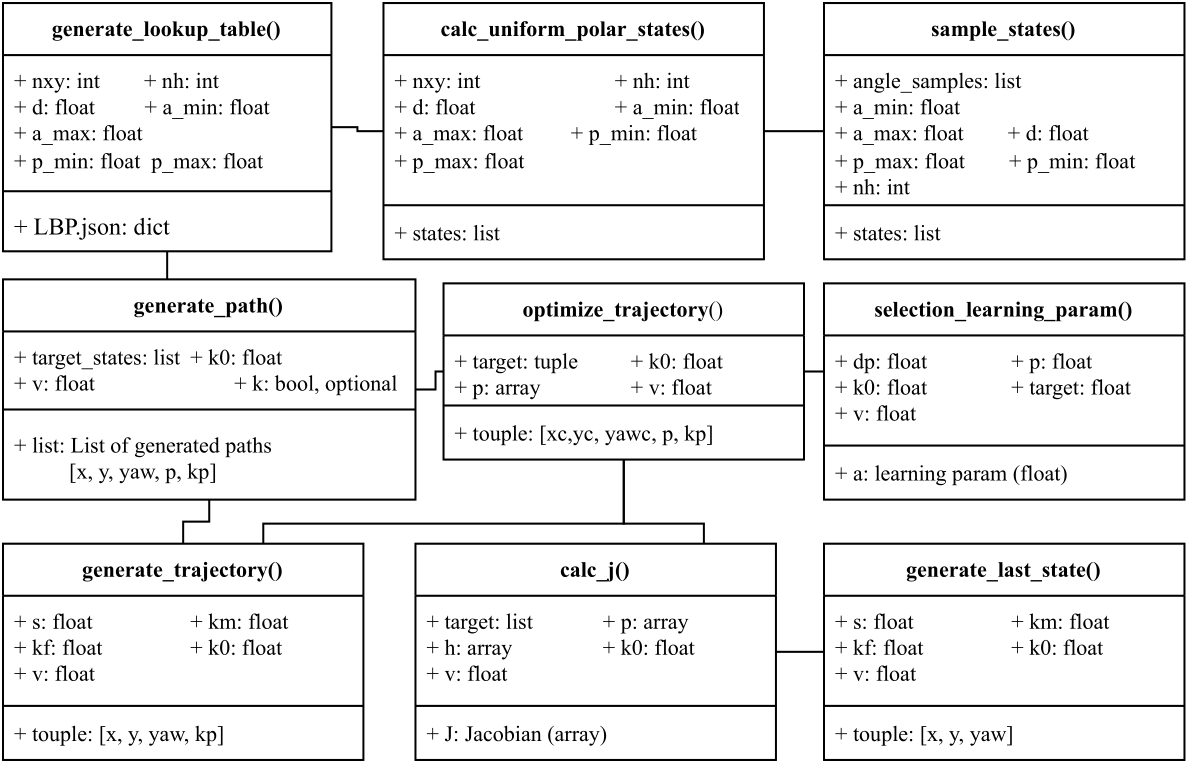
- LBP: Lattice Based Planning. Pre-computes feasible trajectories to reach certain configurations. Then, given a desired trajectory, chooses the pre-computed trajectory that differs the least from the desired one, and follows its commands.
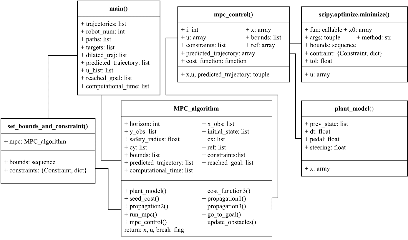
- MPC: Model Predictive Control. In each timestep, a simulation is performed forward in time. Then, the input for each timestep is optimized to minimize a cost function, throughout the entire prediction horizon.
- MPPI: Model Predictive Path Integral control. In each timestep, a batch of simulations is performed forward in time. Then, each trajectory is weighted based on a cost function and updates the distributions from which to sample. The weighted average of the inputs is performed at the first timestep, and the process is repeated.
The implementation
The lab's setup
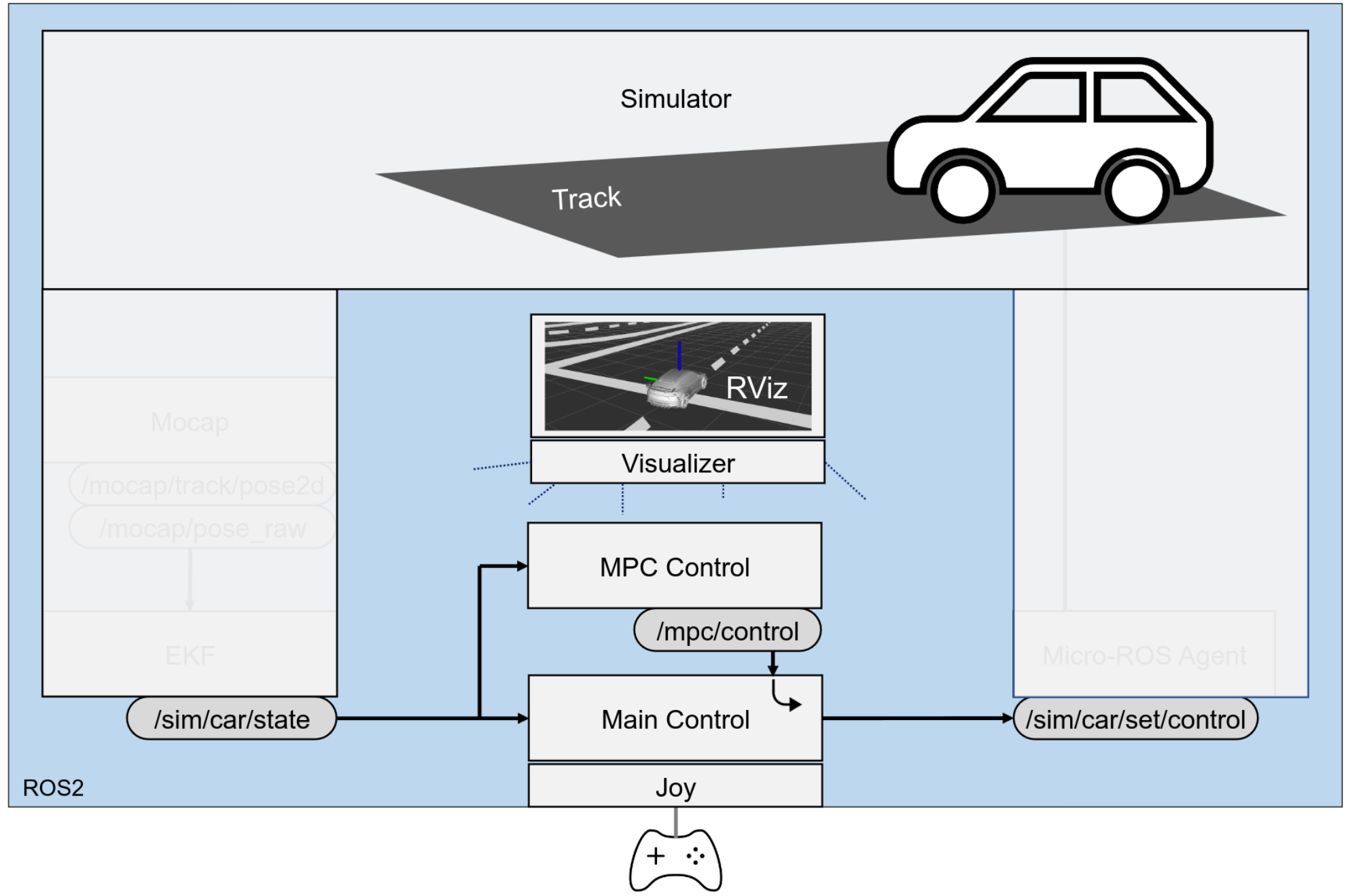
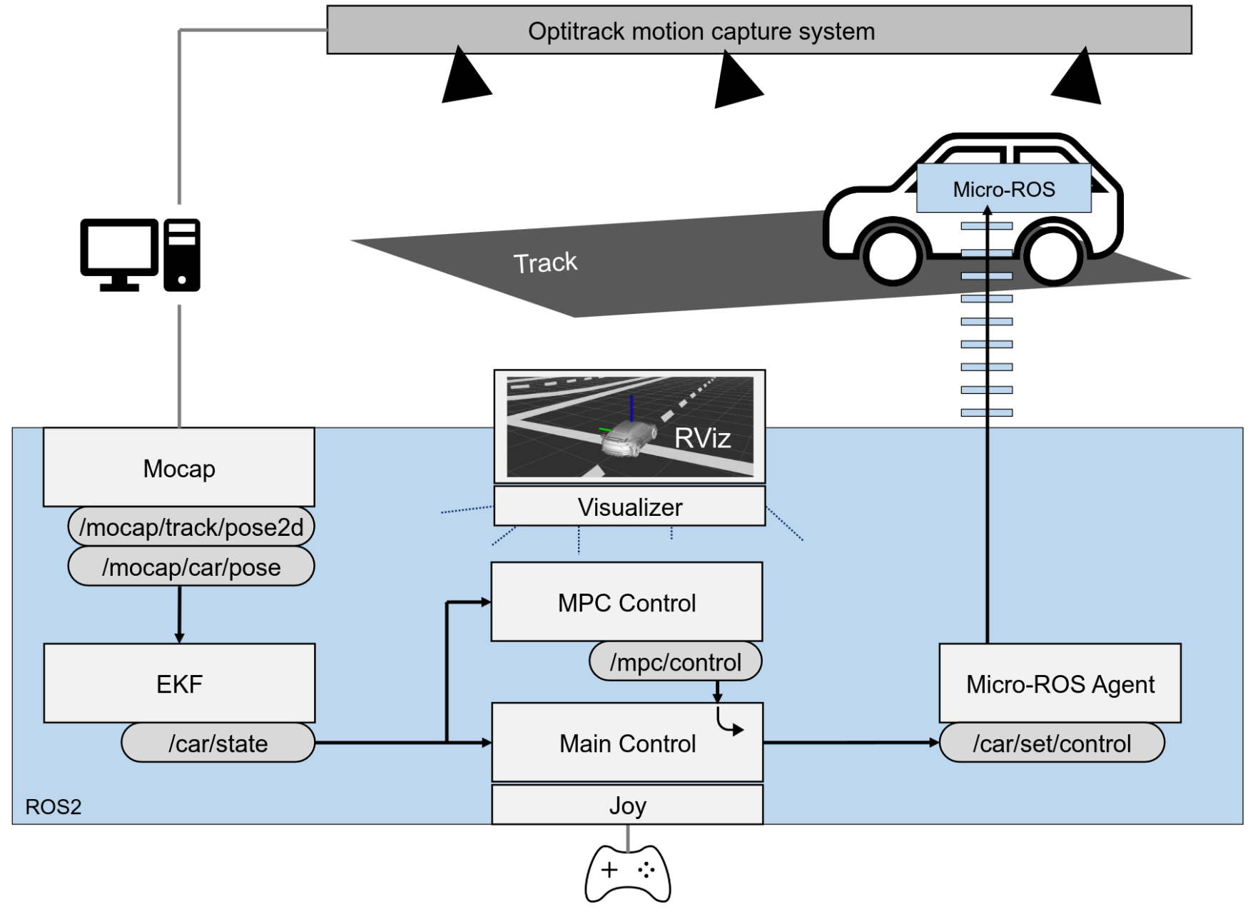
In the lab, there was a setup with motion capture cameras that could track accurately the position of the mini-cars. However, preference was put into working with the simulated environment, as it allowed for parallel advancements on different projects without overlapping usage of the resources.
Both of the environments were build to work with ROS2, so the algorithms could be tested in both environments without any changes in the code. The ROS2 structure of both environments can be seen below:
Early stages: Making the multi-car system
Since up to this point there had not been any previous project in the lab with the objective of controlling multiple cars, the system was not ready for such a task. The first step was to make the system multi-car. This was achieved by taking the existing code for a single car and running it in parallel for as many cars as desired. This was not as simple as running N instances of the same code, as some of the information to be transmitted had been hardcoded for a single car.
Bringing the system from Python to ROS2
Now that the lab simulator was ready to take multiple cars, it was time to modify the existing implementation for the collision avoidance algorithms.
Initial implementation
The initial implementation of the algorithm included everything needed to run both with ROS2 and without it. Nonetheless, the provided code was not made in a modular manner. This proved to be a nuisance when porting the algorithms to the lab's ROS2 simulator.
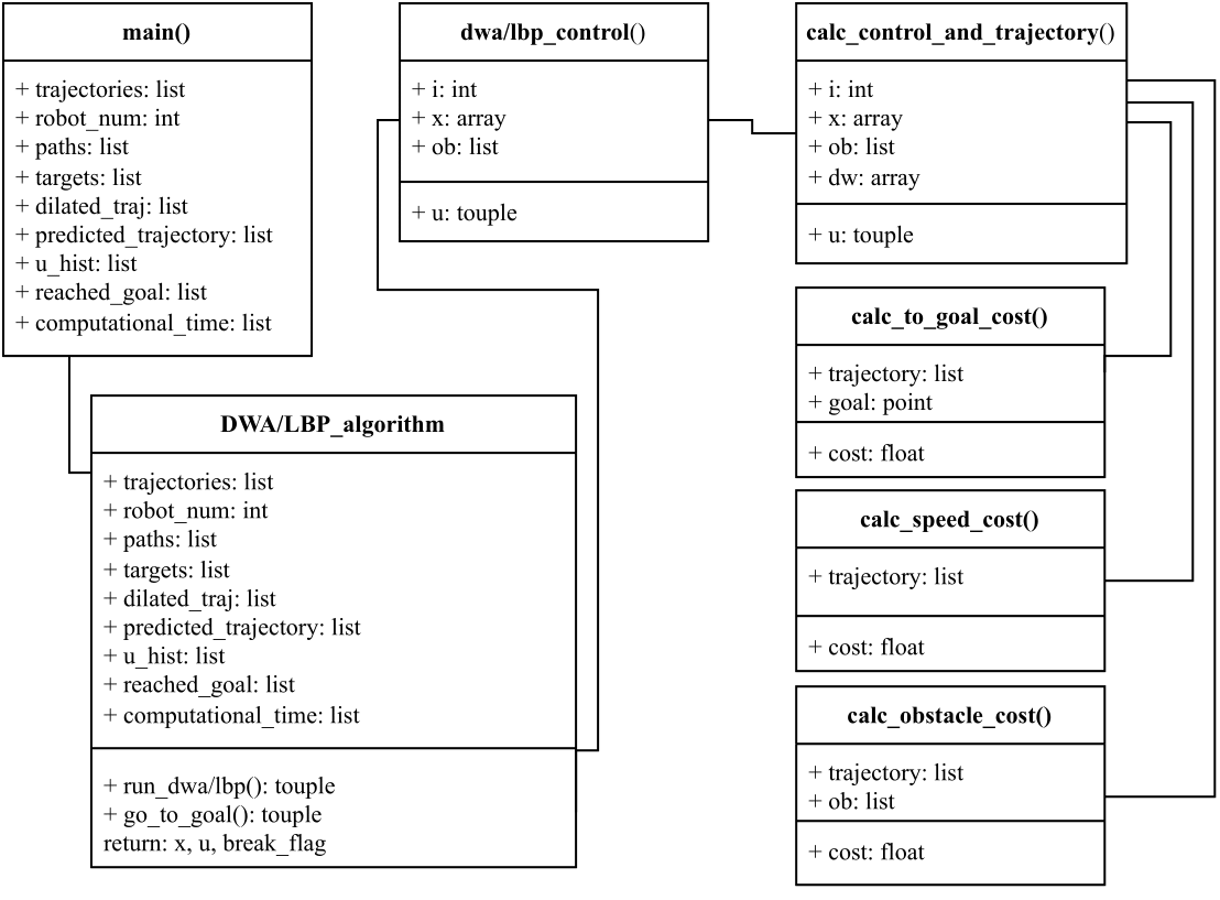
The initial implementation for each of the algorithms can be seen below:
Final implementation
After porting the system to a ROS2 architecture that would work with the setup on the lab, the node structure can be seen in the UML diagram below:
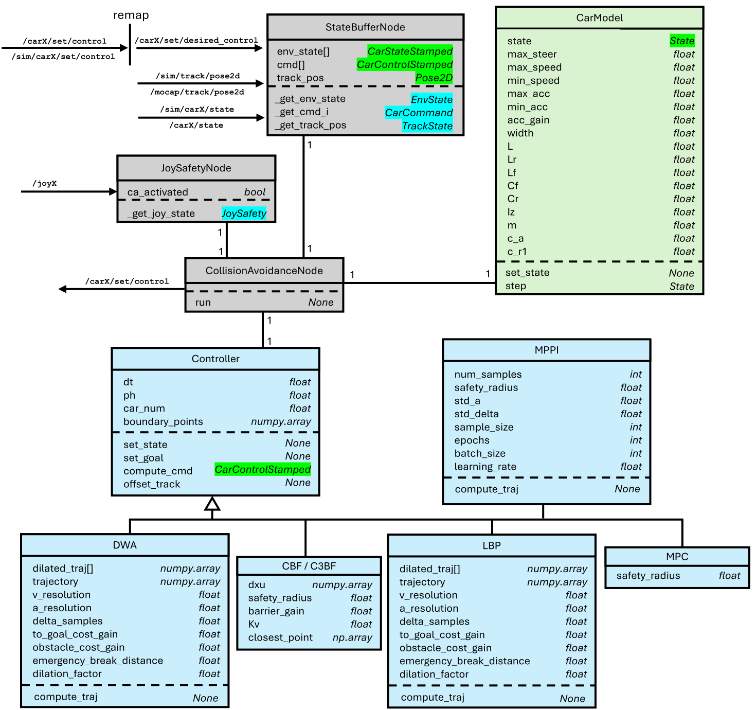
In the diagram, classes are grouped by their functionality within the system:
- Gray: Classes that require communication with ROS2 topics/services.
- Blue: Classes that represent the main collision avoidance algorithms.
- Green: Classes that represent the car.
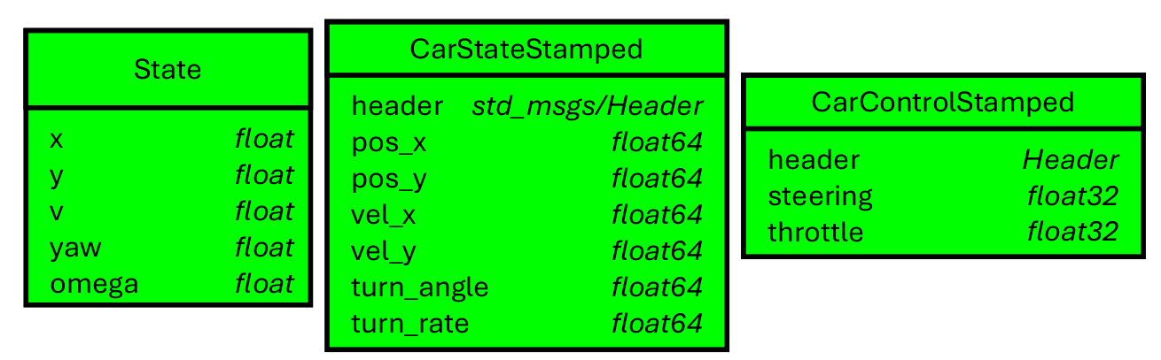
Some variables as well as some return types from functions can be seen highlighted in green the diagram. This is because their type is a non-standard one, so it has been documented in the image below. Only the definition of geometry_msgs/Pose2D and std_msgs/Header were not included, as they are standard ROS2 types.
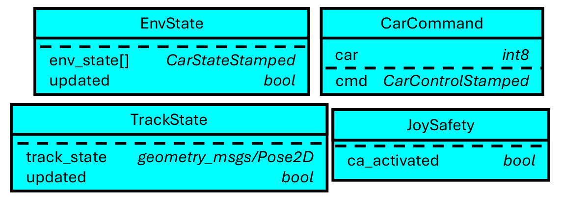
Additionally, the types that were highlighted in light blue had to be custom made to be the response of a ROS2 service. Since they are not standard ROS2 types, they have been documented in the images below.
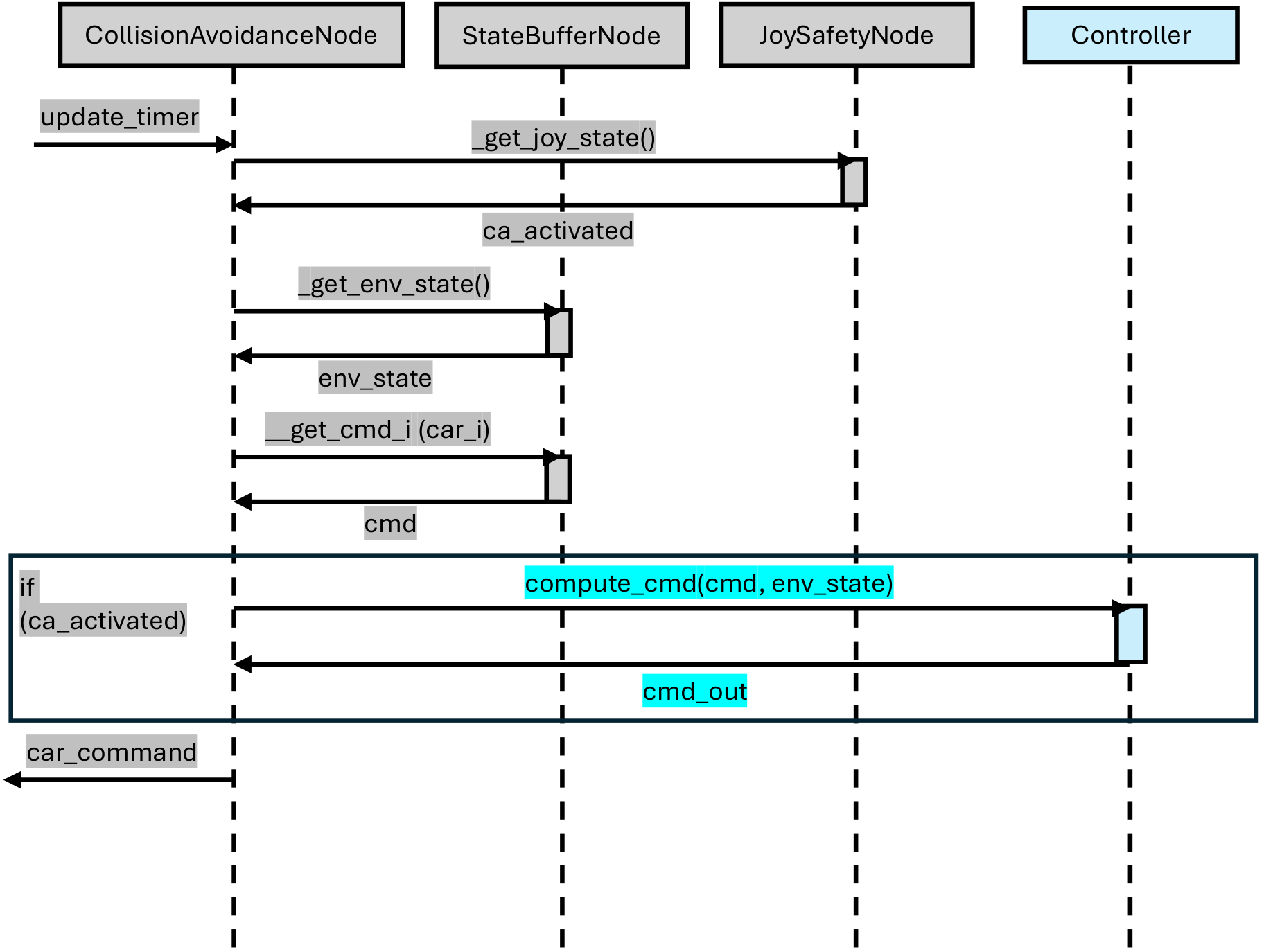
For a more visual representation of what happens in an iteration of the algorithm, the diagram below was made. The steps that are followed by the algorithm are the following:
- When it's time to send a command to the car, a boolean in CollisionAvoidanceNode is set to True, so that the main loop can perform its computations.
- A query is sent to JoySafetyNode, to check if collision avoidance is activated. If not, the node returns the desired control from the user.
- The state of all cars is queried via StateBufferNode, and together with the desired control for the car, it's sent to the collision avoidance controller.
- The collision avoidance controller returns a command that will not end in collision whilst resembling the desired command as much as possible.
- The command is sent to the car (the safe one if collision avoidance is active, the desired one otherwise). The boolean is set to False again, making the main loop wait until the boolean is activated again.
Results
A system where cars can stop colliding with a press of a button was achieved, as well as a system where multiple cars can be controlled at the same time. Watch the video below to see the system in action.
In the videos below, one can observe the performance of each of the implemented algorithms in simulation. As it can be seen, not all of them perform as expected. Hence, not all were tried on the real system.